Photo3D window
- The following window appears, when you invoke the Photo3D system.
- origin submode
- axis submode
- scale submode

figure I.1
Main Drawing Area is used to display photographs, 3D models and various kinds of objects. Above the Main Drawing Area, there are several interactive tools whose names are shown in the figure I.2.

figure I.2
Menu Tabs consists of seven menu tabs. Each tab corresponds to
an operation mode. When you start Photo3D, the File tab is selected
as default and its children menu buttons are shown.

Tool Bar consists of three menu buttons. They are used in common
in multiple operation modes.
Prefix Window is used to modify behaviors of various kinds of
operations by entering a numerical value in it. For example, by setting
a value 0.01 in it the mouse cursor gains as 1/100 distance compared to
the default setting value 1.0, thus enables you to operate precisely.
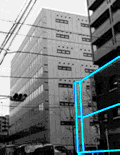
Thumbnail Window shows the list of photographs you are working
with. Bright blue rectangle indicates that the enclosed photo is selected
for the current work. The original counterpart is displayed in the main
drawing area.

In Message Window prompt messages and error messages are displayed. Error messages are shown in red, accompanied with a sound of warning.
Example:
Some of seven modes have its submodes. Menu buttons corresponding
to submodes are grouped together and enclosed in a bevel to indicate they
are submode group. Only one of them can be selected at a time.
1. File
Project and related files
A project is a set of data used to create model by Photo3D. It consists of photo image data, calibrated data, 3D model and texture mapping data. Calibrated data include:1. relation between photograph and real world specified by calibration step
2. relation among photographs specified by positionning step
A project is saved as a project file and related graphic image files, which are copies of source photo data and texture files. A project file has file name extension ".p3d". Related graphic files have extensions such as ".jpg" or ".bmp" depending on the format type. They are saved in the same directory as the project file and have automatically generated names which are related to the project file name.
Menu buttons in File tab


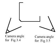


 ideal camera angle